Bones
Although bones are generally used to deform the skin on a virtual creature, I also found bones to be very useful for creating mechanical linkages to animate. We wont actually show the bones, but we will use bones to connect moving parts as sub-directories. Open Joints_08_10_2012_pm4.3DC (720 kB) and look at the directory structure.
In RoboWorks and other programs, a rotational element is placed between groups to create linkages. In 3DCrafter, bones placed in the hierarchy provide the same function. Sub-groups are used to define the extensions past each bone. One word of caution though, since we are not using a skin, do NOT enable the bones, because we do not want to deform the mechanical parts, we just want to create linkages.
 We can give the directories unique names later, but notice that Group222 contains a bone and other shapes. These shapes as a group are linked to a sub-directory named Group which has another bone and other shapes. Because each group has a bone, they are connected by the type of bone being used. Here we have used standard bones which act as hinges, or to say have a range of motion shaped like a cylinder. This is true from the uppermost Group through all of the sub groups. When Group2 is moved, the attached Group22 follows along at the end of Group2's bone.
Let's start with a new 3DCrafter file. We will start by placing a cube in position near the center of the scene. Drag the cube from the Component Panel to the center of the layout. Right click on the cube to scale to size X: 1.2, Y: 0.25, Z:1.2 . Select black (or any other color) from the Materials Panel and select fill to color the cube. You can use the icons on the right hand side of the layout for fill, (paint can), and then the Component Selection Tool (arrow).
 Select the heiarchy tab in the Properties and Information panel and click on the Group you just created. Then click on the third tab, the Component Properties Tab, and enter the location for the block as shown here. You could just as easily used the mouse to locate the cube, but precise positioning gives a better indication of where other groups of shapes will fit.
 Now is the time to add a bone to the group. We will drag a standard bone to the layout and then position it where we want it. After that we will move the cube into the group with the bone. The cube will then become "attached" to the bone. The next sub-group will become attached to the pointed end of this bone. Since we know the exact location of the cube, it will be easy to resize locate the bone in the middle of the cube pointing up.We want the end of the bone slightly above the cube to create a hinge radius down to the cube. At this time the bone is in a separte group that we can use for positioning.Select the bone group from the heiarchy tab, and then select the properties tab.
 It would be good practice to use the Red, Blue, and Green Navigation Controls at the bottom of the scene to locate the bone in the approximate location in the cube. Once located, the group Properties tab should be pretty close to the numbers on the right. If you do move the box before adding the bones, then you will need to reposition the box prior to entering the data on the right for the bone group.
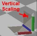
 Now simply drag the cube into the group contaning the bone to complete that group. The empty group where the cube was contained will simply dissapear. Your heiarchy should now look like the image on the left. And your scene should look like the image below. You can vertically scale the bone with the navigation tool at the bottom right to set the location of the top of the bone.
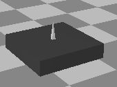
Something that took me a while to grasp, was that since the bone is the determining object in the group, other objects will be locked to the bone position. So position the bone first and drag other shapes into the group with the bone, not the other way around.
Drag a second standard bone into the scene and locate it at a 45 degree angle as shown below.

 Drag this group into the previous group to make it into a sub-group of the previous group. The second bone is now attached to the first bone. Move the first group with the positioning tool and the second bone follows. Reposition the first group to (4.5, .35, 6). Select the sub-group and rotate it with the blue rotating tool to see the effect. The second bone can also carry a third bone and so forth.
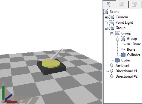
There are times when you will need to remove a shape from a group and have it stand alone. This is what we will do with the cube in the first group. Rather than use the Ungroup command, we will right click on the cube, select Edit and Cut. Then right click on the uppermost element in the hiearchy, scene, edit, paste. This will move the cube and a bone to a separate group that is not a sub-group. Delete the new group bone by clicking on it and pressing the delete key.
Now create a cylinder to replace the cube in the first group. Create a cylinder and scale it to XYZ (1.0, 0.2, 1.0) and position it at XYZ (4.5, 0.6, 6.0). Then drag the cylinder back into the first group. We also want the group containing the cylinder to be a subgroup of the group containing the cube. This way, moving the base cube will move all of the subgroups with it. So drag the cylinder group into the cube group. I often will save the current scene and then reopen the scene just to get the hiearchy to look right after changes. It's not necessary, but it does seem to help. Your layout should like the one below.